
Before a single aircraft part gets manufactured, engineers already know exactly where it might crack under pressure. Before a car goes into a crash test, the simulation has already run hundreds of times. That’s not magic – that’s Finite Element Analysis at work.
If you’re new to FEA, this guide breaks it down in plain language. No heavy mathematics, no jargon overload.
What is Finite Element Analysis?
Here’s the simplest way to put it:
FEA is a computer simulation technique that tells you how a physical object – a bracket, a shaft, a bridge beam – will react when you put it under stress, heat, pressure, or vibration.
Instead of building a part, testing it to failure, and starting over, you run the test on a computer first. The software predicts where stress concentrates, where deformation happens, and whether the design holds up or fails.
The technique behind it is called the Finite Element Method (FEM). FEM works by slicing the geometry into thousands of small pieces called elements, connecting them at points called nodes, and solving mathematical equations across each one. When all those small solutions come together, you get a complete picture of how the whole structure behaves.
A rough analogy: imagine assessing the strength of a mosaic wall by testing each tile individually. Study enough tiles under enough conditions and you’ll know where the wall is weak before anyone leans on it.
How Does the FEA Process Actually Work?
Most FEA workflows follow five stages. Here’s what each one involves:
Step 1 – Create the CAD geometry
Everything starts with a 3D model built in CAD software like PTC Creo. This is the digital shape of whatever you’re analysing – a component, assembly, or structure.
Step 2 – Meshing the model
The geometry gets divided into small elements – triangles, tetrahedra, or bricks depending on the shape. This mesh is what the solver actually works with. A finer mesh gives more detailed results but needs more computing power. Engineers decide how fine to go based on where accuracy matters most.
Step 3 – Define the real-world conditions
This is where the simulation gets grounded in reality. Engineers assign:
- Material properties – steel, titanium, plastic, whatever the part is actually made from
- Applied forces, pressures, or temperatures
- Fixed points, joints, or supports that constrain the model
- Any other physical conditions the part will experience in use
Step 4 – Run the solver
The FEA software – tools like MSC Nastran or Creo Simulate – runs through the calculations across every element in the mesh. This can take seconds for a simple part or hours for a large, complex assembly.
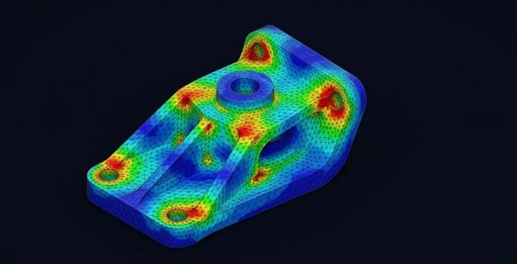
Step 5 – Review the results
Output comes in the form of colour-coded maps showing stress distribution, displacement, temperature gradients, or deformation. The hotspots – areas under the most strain – show up clearly. Engineers use this to refine the design before it ever goes to manufacturing.
The Main Types of FEA
Not every analysis is the same. The type you run depends on what question you’re trying to answer:
- Structural static analysis – How does the part behave under a constant, steady load? Good for machine components, frames, and pressure-bearing parts.
- Thermal analysis – How does heat move through the component, and does that heat create stress or deformation?
- Modal analysis – At what frequencies does the structure naturally vibrate? This matters a lot in rotating machinery and aerospace components.
- Fatigue and durability analysis – How long will the part last under repeated loading before it develops cracks or fails?
- Fluid-structure interaction (FSI) – How do fluid forces act on a structure? This overlaps with CFD and is common in turbine blades, pipelines, and marine structures.
Where FEA Gets Used in the Real World
Finite element analysis shows up across pretty much every engineering sector:
Aerospace – Stress testing of fuselage frames, thermal analysis on engine components, fatigue prediction on landing gear and fasteners.
Automotive – Crash simulation, suspension durability, brake rotor life, NVH (noise, vibration, harshness) testing. Most of what goes into a modern vehicle has been through FEA.
Civil and structural engineering – Bridge load analysis, building response to seismic activity, crane certification, and underground pipeline integrity.
Biomedical – Hip and knee implant stress analysis, prosthetic performance under body weight and movement, and cardiovascular device testing.
Heavy industry – Gearbox and drivetrain analysis, pressure vessel checks, and equipment used in mining, energy, and manufacturing.
Tools like MSC Nastran and MSC Adams – both available through CreoTek India – are standard across these industries for exactly this kind of work.
Why Engineers Actually Use FEA
A few practical reasons it’s become routine in product development:
- You catch problems early, when fixing them costs far less than after tooling is cut
- You can test conditions – extreme heat, seismic loads, impact forces – that would be dangerous or expensive to replicate physically
- Design iterations happen faster because you’re not waiting on physical prototypes
- Results support regulatory submissions and certification requirements
- You can trim material where it isn’t needed, cutting weight and cost without guessing
Questions Engineers Usually Ask About FEA
What’s the difference between FEA and FEM?
FEM is the mathematical method. FEA is the process of applying that method to a real engineering problem using simulation software. Same idea, different angles – FEM is theory, FEA is practice.
What software do engineers use for FEA?
MSC Nastran, Abaqus, Ansys Mechanical, and Creo Simulate are among the most widely used. In India, MSC Nastran and Adams (both distributed by CreoTek India) are common choices for structural and dynamic analysis.
Is FEA only for mechanical engineers?
Not at all. Civil, aerospace, biomedical, and even electrical engineers use FEA regularly. The physics change depending on the field, but the core approach stays the same.
How accurate is FEA?
It depends on how well the model is set up. Get the mesh quality, boundary conditions, and material data right, and FEA results track closely with physical testing. That’s why it’s accepted for product certification in industries like aerospace and medical devices.
Final Thoughts
FEA has taken a lot of the guesswork out of engineering. You still need strong engineering judgement to set up a simulation correctly – but once you do, the insight you get is hard to match with any other method.
If you’re looking to run FEA simulations on your own designs, CreoTek India offers MSC Nastran, MSC Adams, Creo Simulate, and a range of other simulation tools built for serious engineering work. Check out our simulation software