
If you’ve ever watched smoke curl off a candle and wondered how engineers predict the same behaviour inside a jet engine – that’s essentially what CFD does. Not magic, not guesswork. Math, run on computers, at a scale that physical testing alone could never match.
What is CFD Analysis?
CFD analysis, or Computational Fluid Dynamics analysis, is the use of numerical methods and algorithms to solve equations that govern fluid flow – liquids, gases, or anything in between. Engineers use it to simulate how a fluid moves through or around a design before that design is ever built or tested physically.
The term “fluid” here covers more than water. Air around a car body, coolant through a heat exchanger, combustion gases inside a turbine – all of these are fluid problems that CFD can model.
At the heart of every CFD simulation are the Navier-Stokes equations. These partial differential equations describe conservation of mass, momentum, and energy in a moving fluid. They’ve been around since the 1820s. What changed in the last few decades is computing power – enough to solve these equations across millions of small cells simultaneously.
How Does a CFD Simulation Actually Work?
The process breaks down into three distinct phases.
Pre-processing is where everything starts. The engineer imports a 3D model of the component – a duct, a valve body, a car hood – and divides the fluid domain surrounding or inside it into a mesh. This mesh is a grid of small cells (tetrahedra, hexahedra, polyhedra) that cover the entire fluid region. The smaller the cells, the higher the resolution of results, but also the higher the computational cost. Getting the mesh right is genuinely one of the harder parts of CFD work.
Solving is what the software does next. Boundary conditions are defined: inlet velocity, outlet pressure, wall temperature, fluid properties. The solver then iterates through thousands of calculations, updating velocity, pressure, and temperature values at every cell until the solution converges – meaning the changes between iterations drop below a defined threshold. This can take minutes or days depending on the complexity.
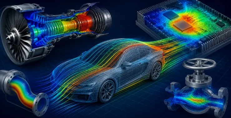
Post-processing is where results become visible. Colour-mapped pressure contours, velocity streamlines, temperature gradients – this is the stage where the simulation tells you what’s happening and why. Engineers look for things like flow separation, pressure drops, hotspots, or turbulent recirculation zones that would otherwise be invisible until a prototype fails.
What Does CFD Analysis Tell Engineers?
The short answer: a lot, with specificity.
Rather than testing a prototype and observing that it overheats, CFD shows exactly where thermal energy accumulates and why. Rather than realising in wind tunnel testing that a component vibrates at certain flow speeds, CFD can flag the resonance risk before a physical model exists.
Specific outputs from a CFD run typically include pressure distribution across surfaces, velocity profiles through cross-sections, turbulence intensity and kinetic energy, heat flux and wall temperature distribution, and drag and lift coefficients for aerodynamic components.
Each of these can feed back into the design. If the simulation shows high-pressure loss through a pipe bend, the geometry gets modified and re-run. This iterative process is faster and cheaper than physical prototyping, especially in early design stages.
Where is CFD Analysis Used?
The industries using CFD regularly are broader than most people assume.
Automotive and Aerospace: External aerodynamics is the obvious one – CFD shapes the bodywork of production cars and the fuselages of commercial aircraft. But internal flows matter just as much: intake manifolds, cooling ducts, HVAC systems inside cabins, heat exchangers.
Power Generation and Turbomachinery: Gas turbines, steam turbines, and compressors all depend on CFD for blade design and cooling analysis. The flow paths are complex, the temperatures are extreme, and physical testing is expensive. CFD reduces the design cycle significantly.
Electronics Cooling: As component densities increase, thermal management becomes a first-order design problem. CFD simulations of airflow through server racks, PCB enclosures, and power electronics help engineers ensure nothing runs too hot.
HVAC and Building Ventilation: Air distribution inside buildings, clean rooms, and hospitals is simulated with CFD to ensure comfort, energy efficiency, and air quality. This has become more relevant since the pandemic, with ventilation design under closer scrutiny.
Oil, Gas, and Process Industries: Pipe flow, multiphase flows, mixing vessels, heat exchangers – CFD is embedded in process engineering workflows.
Biomedical Engineering: Blood flow through artificial heart valves, drug delivery through respiratory inhalers, and airflow in nasal cavities – even biology has become a CFD domain.
CFD vs Physical Testing: Not a Competition
CFD doesn’t replace physical testing. It reduces the number of physical tests needed and improves the quality of what gets tested.
Physical experiments give you reality. CFD gives you understanding. Used together, they’re more effective than either alone. A well-validated CFD model can run hundreds of parametric studies – changing inlet angles, wall roughness, operating temperatures – in a fraction of the time that physical setups would require. Only the most promising configurations go to physical validation.
This is particularly relevant for Indian manufacturers, where reducing prototype cycles directly affects time-to-market and product development costs.
Common CFD Software and What to Look For
The two approaches in commercial CFD software are solver accuracy and workflow integration. Some platforms lean on powerful meshing and physics breadth; others prioritise tight integration with CAD tools so that geometry changes flow smoothly into simulation.
Hexagon’s Cradle CFD, available in India through CreoTek India, is designed with both in mind. Its scSTREAM and scFLOW solvers handle everything from external aerodynamics to thermal management of electronics, with a practical workflow that doesn’t require a PhD to navigate. For manufacturers already working within a simulation-driven product development process, it connects cleanly with other CAE tools in the Hexagon MSC ecosystem.
Other well-known platforms include Ansys Fluent, OpenFOAM (open source), STAR-CCM+, and Simcenter. The right choice depends on the physics involved, the level of automation needed, and how the simulation team is structured.
A Few Things Worth Knowing Before You Start
CFD is powerful, but it’s not a black box you feed geometry into and receive truth from. Results are only as good as the mesh quality, the turbulence model chosen, and the accuracy of boundary conditions. Turbulence modelling in particular involves assumptions – k-epsilon, k-omega SST, LES – and different models perform better in different flow regimes.
Validation against physical data is essential before trusting any CFD model for design decisions. This is less of a limitation than it sounds. Once a model is validated for a particular class of problem, it can be used with confidence across a family of similar geometries.
The learning curve for CFD is real. But for engineers who want to move from reactive problem-solving – figuring out why a prototype failed – to predictive design, it’s one of the most valuable skills to develop.
Getting Started with CFD in Your Organisation
For teams new to CFD, the path typically starts with training on a commercial platform, a few guided simulation projects on known problems (pipe flow, heat sink cooling), and then gradual expansion into product-relevant cases.
CreoTek India supports engineering teams across Delhi NCR and India with Hexagon Cradle CFD licensing, implementation, and technical training. If your design process still relies primarily on physical prototyping for fluid and thermal problems, CFD simulation is worth a serious look.